
 When I was a teenager, I built an AM radio station out of tubes, soup
cans, and spare parts. The schematic for the station still exists to
this day, on the inside of the medicine cabinet at my mother's house,
where I grew up. That's a picture of the inside of the cabinet door
over on the right. The station was disassembled when an FCC van was
spotted cruising the area. They were probably chasing CB'ers using
unlicensed power amps, but it scared me silly, and the station went
into the junk bin - in lots of little pieces.
When I was a teenager, I built an AM radio station out of tubes, soup
cans, and spare parts. The schematic for the station still exists to
this day, on the inside of the medicine cabinet at my mother's house,
where I grew up. That's a picture of the inside of the cabinet door
over on the right. The station was disassembled when an FCC van was
spotted cruising the area. They were probably chasing CB'ers using
unlicensed power amps, but it scared me silly, and the station went
into the junk bin - in lots of little pieces.
Back then, I broadcast all manner of rock, hard rock, comedy (Cheech and Chong, etc.) and twisted satire across my home town at 1020 AM, "WUMP" (sound of hand slamming the microphone). My sister was an occasional DJ, participating in the lampooning of then-president Richard Nixon and other luminaries.
The station was modeled after a serious pirate that ran from the center of a park area in New Jersey, fighting the government in the forced takeover of people's property for the park. Some science fiction people lived there, and on a visit to them with my mother (who was and still is a literary agent who specializes in science fiction and fantasy) I met the "proprietor" of the pirate station. When he learned that I was an electronics enthusiast, he invited me up to see the station. I went, and I was totally fascinated. Within a few weeks I had one of my own up and running in Milford, Pennsylvania, which is where I lived at the time.
 Later (when I was in my twenties), I obtained an advanced FCC broadcast engineer's license
as well as the top-level amateur radio license (extra-class)
and pretty much "went straight", much as I don't like to admit it.
However, although I obey the FCC rules, I'm on the air again. The FCC
has a number of things to say about unlicensed operation
(here), but the key
issues that apply to me are: You can operate if you...
Later (when I was in my twenties), I obtained an advanced FCC broadcast engineer's license
as well as the top-level amateur radio license (extra-class)
and pretty much "went straight", much as I don't like to admit it.
However, although I obey the FCC rules, I'm on the air again. The FCC
has a number of things to say about unlicensed operation
(here), but the key
issues that apply to me are: You can operate if you...
I meet requirement (a), and (b) isn't really a problem in a town with only one AM and two (other) FM stations.
If you're local to my location in Glasgow (really local!) you'll find my current station (which you can see part of above, left) on 102.7 FM, in stereo. Generally I'm broadcasting rock, hard rock, or 80's tunes but there are smatterings of other themes as well. The quality is as good as, or better than, many commercial stations - I broadcast digital source material exclusively. The station's frequency is crystal controlled by a microprocessor-based synthesized frequency multiplier. It doesn't drift and its right where I want it to be (at the other end of the band from our local stations). If you're in good range of the station, you'll likely get as good performance as your FM radio is capable of.
The image at left is of the synthesizer/modulator portion of my FM stereo station, found at 102.7 Mhz in the FM broadcast band. The picture was taken with my Casio QV-100 digital camera, then cropped and reduced using WinImages, an image manipulation package my company makes. When I think of the Campbell's soup cans that my old AM station was built in, I have to laugh a bit... Then again, it worked just fine. If you are familiar with binary numbers, you can read the frequency off of the DIP switches in the image: 10, 2, 7, or 1010 0010 0111 - which is 102.7
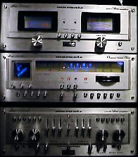 At home, I generally listen to it on my vintage
Marantz stack, and I'm one happy camper. If
I'm working outside my home, I use the stereo in my car or truck, which are both Sonys... nice gear to enjoy my music with.
I never listen to the local country & western (AM 1240, KLTZ) or
schizoid "popular tune" (FM 93.5, KLAN) stations. I might, in a weak
moment, tune in the public radio station (FM 91.9), but their socialist
rantings chase me away in short order. No, my station is the
station for me. "Life Is Good", as my friend
Bob Stormer would say.
At home, I generally listen to it on my vintage
Marantz stack, and I'm one happy camper. If
I'm working outside my home, I use the stereo in my car or truck, which are both Sonys... nice gear to enjoy my music with.
I never listen to the local country & western (AM 1240, KLTZ) or
schizoid "popular tune" (FM 93.5, KLAN) stations. I might, in a weak
moment, tune in the public radio station (FM 91.9), but their socialist
rantings chase me away in short order. No, my station is the
station for me. "Life Is Good", as my friend
Bob Stormer would say.
Although I designed and built the old AM station, I built the FM transmitter from a kit Ramsey Electronics makes, and then modified it slightly to reduce various hum & noise, and to increase the bass response (which is fairly poor, if you build the kit as they supply the parts.) Here are the mods:
Hum Reduction:
If you're thinking of building this kit, do yourself a big favor and obtain a couple of high-Q, medium size (about 1.5 inch in diameter) ferrite cores and wrap both the power cord and the audio cables to the transmitter around them about five to fifteen times, in an evenly distributed spiral. I don't have that many wraps shown here for the audio because I have a cable length problem, but you should try to have as close to 15 wraps as you can anyway. The more wraps, the better this works. Create the wraps in such a way that the core ends up right next to the transmitter jacks, with as little cable as possible coming from the cores to the jacks - in other words, the cores should "hang close to" the back of the transmitter. They (Ramsey) suggest using four .01 caps to bypass the rectifiers in the power supply to reduce powerline induced hum, but that's not even close to sufficient. Use the toroid wrap as well, and you can eliminate a great deal of the significant hum from this source. The problem is that with the little whip antenna right there on the unit, the strength of the RF field is extremely high at the jacks (and along the wires connecting to the unit), and AC hum is carried into the unit "piggyback" on the broadcast signal, rectified in the power section.
Bass Response Improvement:
As the kit is supplied, if you've got even a decent ear for audio, you'll notice a rather profound bass rolloff in the received signal beginning at about 150 Hz. Which, to put it bluntly, sucks. It's easy to fix. Go to Radio Shack (or anywhere you can get parts) and buy a couple of 10 volt (or more... but 10 is good because they're physically smaller) 470 uF electrolytic capacitors, and replace the two audio input coupling capacitors (C17 and C25 as shown in the schematic here), which are 10 uF. There isn't a lot of spare room, and you want to keep the leads short, so get small caps and make sure you don't buy axial lead parts. Be sure to observe the circuit polarity; positive goes to the IC, and negative to the signal jacks. Two things will happen. First, when you turn on the transmitter, it will take as much as a couple of minutes for you to hear any audio, as these puppies take quite a while to charge through the input resistors to a level where the FM modulator IC can work with the audio. Then you'll hear a little distorted audio, and all of a sudden, it'll be great audio. After that, it's good to go. The bass response now goes down to about 20 Hz, clean as a whistle. Isn't that nice?
| Low Power Broadcast FAQ | General Information on Low Power Radio Broadcasting |
| FCC | What the FCC has to say about low power broadcasting |
| Free Radio Berkley | A station, with info about a legal fight for micropower stations |
| FRN | Free Radio Network - check it out... |
| EFF | Electronic Frontier Foundation - General electronic freedom issues |