Beta Address: http://blish.org/sdrdxdoc/controlsbuttons.html
5.33 - GUI Controls
5.33.1 - Sliders
VOL - Audio "Volume"
DCY - Automatic Gain Control "Decay" (AGC recovery speed.) This is set in millisecond units, and is affected by the setting, which allows a choice between linear and logarithmic control.
I/R - "Intercept/RF Gain" Controls receiver sensitivity and sets the ultimate gain floor for the AGC system.
NBT - Noise Blanker Threshold. When / is in use, you generally want to try a setting of around 50.
NBW - Noise Blanker Width. When / is in use, start with 30 and adjust from there.
GRT - "Graticule" (the grid on the signal display) controls relative intensity. Adjust to taste.
BPA - "Bandpass" (the transparent bandpass signal overlay) controls relative intensity. Adjust to taste.
TXS - "Transmit Squelch" When is on, sets the level at which strong signals mute the receiver.
SQL - "Squelch" Sets the level at which the receiver mutes in FM mode, or in AM mode when is on, or in an SSB mode. If is off, muting will be applied by measuring the amount of noise in the signal.
CWO - CW Offset (morse code tone) This control allows you to shift CW or SSB tonality to your taste, without changing the signal's tuning or the passband position. Most useful in CW operations. Veteran CW operators will find its use immediately familiar. I suggest 700 Hz as a good starting point for CW operations.
F - "Frequency" (notch filter frequency) This slider affects only the currently selected notch, which in turn is indicated by a red LED.
Q - "Q" (notch filter width) This slider affects only the currently selected notch, which in turn is indicated by a red LED.
Lpf - "Low Pass Filter Frequency", enabled by . →Right-click for AGC needle trim.
Hpf - "High Pass Filter Frequency", enabled by .
I - Waterfall palette Intercept readout / slider. This controls at what color signals intercept the waterfall color palette.
C - Waterfall palette Contrast readout / slider. This controls how many colors a signal of a given amplitude uses from the waterfall palette.
TRK - How many peaks to track when is on. must be on. Peak tracking is high speed and is primarily intended for use in narrow bandwidth carrier identification. Use in wide bandwidth displays may result in marker scatter such that they are difficult to read.
5.33.2 - Knobs

Knob 1
Top knob - This knob is dedicated to controlling the aux scope. In mode, it sets the gain for channel 1 (the top channel, which carries demodulated audio.) In mode, it sets the center frequency for the X/Y scope filters. In , , , ,  3D and modes, it sets the fixed frequency span if is on. In mode (except in ), it sets the RF span (and indirectly, the FFT size.)

Knob 2
Bottom knob - This knob is dedicated to controlling the aux scope. In mode, it sets the gain for channel 2 (the bottom channel.) In mode, it sets the difference (or "shift") between the two filter frequencies for the X/Y scope filters. In and modes, this knob has no function. In and 3D modes, this knob sets channel gain. In mode, this knob shifts the center frequency.
5.33.3 - Buttons
An Active Tooltip
- Enable / Disable tooltips. SdrDx features comprehensive tooltips for every control on the main GUI. With on, hovering the mouse pointer over anything in the control section of the GUI will pop-up a descriptive tip describing the control.
The feature has four states:
- — display no tooltips except memory if is on
- — display tooltips
- — Same as except tips to RTTY area
- — Same as except tips to RTTY area
- When on, SdrDx will start with the application window set to the target design size, which is 1280 x 1024. When off, SdrDx will remember whatever window size you have set the application to, and will start at that size and position.
- Process data from a network SDR. Right-click for network SDR frequency correction dialog. Values are in Hz.
- Opens the Dual Antenna Settings dialog. This allows you to control phasing, nulling, and noise reduction with two antennas and a supported dual-input SDR. Details here.
- Process data from the s FCD (s nobreak →Right-click for settings)
- Auto Waterfall Intercept. SdrDx tries to keep waterfall colors where you set them, even when the noise floor changes. Works both in-band and across band changes. Right-clicking allows you to set the rate of noise-floor tracking.
- Previous, Next BroadCast band. SdrDx knows about quite a few broadcast bands.
allows you to turn the mouse pointer snap-to-frequency on and off as desired. Saves lots of trips back and forth with when you're switching back and forth between different kinds of DXing in the same session.
- Previous, Next Amateur Radio band (affected by , below.) SdrDx knows about all the US amateur LF, HF, VHF and UHF bands as well as some of the EU bands.
Display DataBase. →Right-click for settings. This affects both internal database display on the spectrum, and any external commands received via TCP / UDP.
- Center frequency LocK. Prevents you from changing the center frequency. Can turn on automatically, for instance when > or are operated. Affects memories, VFOs, network commands, and manual frequency adjustment via the center frequency control.
- Keyboard Lock. Allows you to prevent unintended keystrokes from altering the settings of SdrDx. Also, clicking this so that it is not illuminated ensures that the application sees keystrokes. There are some controls, in particular the main frequency readouts, that can "steal" keystrokes, effectively making the program deaf to keyboard commands. This button re-directs keyboard input to the command system when not illuminated. If the program becomes unresponsive to keyboard commands and is illuminated, press once. Otherwise, press twice. You can set several features for keyboard locking; →Right-click to access those features.
- Keystroke reference and re-mapping dialog. Reference snd remapping capability for all of the keystroke commands set up and available within SdrDx.
- Opens this online manual to the table of contents if a network connection is available. So when you're learning the software, try to make sure there is such a connection!
- Set Font Size (for RF Spectrum Fonts) Left and right click to change. Also mapped to f and ^ F
- Set Audio Latency. Left-clicking reduces latency; Right-clicking increases it. Setting is shown in info1, inside curly braces as {2}, {4}, {8} or {16}.
- execute default name "ss" program in home directory as detached process with a parameter of 1. You can use this to fire off just about anything you can think of. Just make ss (or any other name - you can set the name by right clicking on any EX button) a Python or Perl or other script and do whatever you want.
Let's say your name is John Doe. Under OS X / MacOS, your home directory is probably then:
/Users/johndoe/
While under Windows XP, your home directory is probably:
c:\Documents and Settings\John Doe\
...so these locations are where your script or executable must be located. The content of must be simply the script name or executable name. Remember that a parameter is passed to the script or executable, 1
See this page for details on setting this up for Windows XP
- execute default name "ss" program in home directory as detached process with a parameter of 2. You can use this to fire off just about anything you can think of. Just make ss (or any other name - you can set the name by right clicking on any EX button) a Python or Perl or other script and do whatever you want.
Let's say your name is John Doe. Under OS X / MacOS, your home directory is probably then:
/Users/johndoe/
While under Windows XP, your home directory is probably:
c:\Documents and Settings\John Doe\
...so these locations are where your script or executable must be located. The content of must be simply the script name or executable name. Remember that a parameter is passed to the script or executable, 2
See this page for details on setting this up for Windows XP
- execute default name "ss" program in home directory as detached process with a parameter of 3. You can use this to fire off just about anything you can think of. Just make ss (or any other name - you can set the name by right clicking on any EX button) a Python or Perl or other script and do whatever you want.
Let's say your name is John Doe. Under OS X / MacOS, your home directory is probably then:
/Users/johndoe/
While under Windows XP, your home directory is probably:
c:\Documents and Settings\John Doe\
...so these locations are where your script or executable must be located. The content of must be simply the script name or executable name. Remember that a parameter is passed to the script or executable, 3
See this page for details on setting this up for Windows XP
- execute default name "ss" program in home directory as detached process with a parameter of 4. You can use this to fire off just about anything you can think of. Just make ss (or any other name - you can set the name by right clicking on any EX button) a Python or Perl or other script and do whatever you want.
Let's say your name is John Doe. Under OS X / MacOS, your home directory is probably then:
/Users/johndoe/
While under Windows XP, your home directory is probably:
c:\Documents and Settings\John Doe\
...so these locations are where your script or executable must be located. The content of must be simply the script name or executable name. Remember that a parameter is passed to the script or executable, 4
See this page for details on setting this up for Windows XP
- RF Waveform Fill. Left-clicking changes the fill state to on or off. You can set the fill color by →Left-click.
- Peak Hold function for spectral and carrier scope modes. Adjust peak hold by right-clicking .
... - Ten of the 25 memories (press shift to store) If you press shift+control plus this button (or key), then SdrDx will emit a TCP message of the form macro:N, where N is the key number from 1 to 25.
F1 ... - Ten of the 25 memories (initially set to presets -- press shift to store.) If you press shift+control plus this button (or key), then SdrDx will emit a TCP message of the form macro:N, where N is the key number from 1 to 25.
- Enable overload detection for FFT math. See
 OVL - Overload detection (A/D (and optionally FFT)) indicator. Lights when more than two volts appears at the input of the A/D. Also lights if the signal is extremely large and the internal math is running out of headroom, if is active.
- SDR configuration dialog. Allows you to set parameters for RFSPACE SDRs.
- DiSPlay configuration dialog. Allows you to set the FFT size, averaging, mouse click resolution, display rates and triage settings, among others. See the dialog image below. Mouse click resolution affects the rate at which the mouse roller adjusts the tuned frequency, as well as the frequency interval a click on the spectrum resolves to.
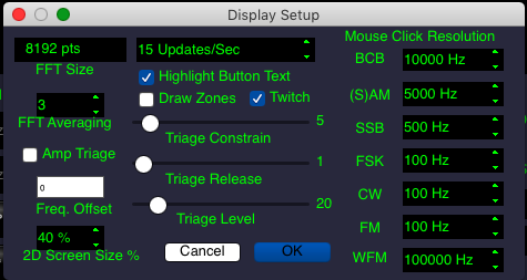
Display Dialog
- DeMoDulator configuration dialog:
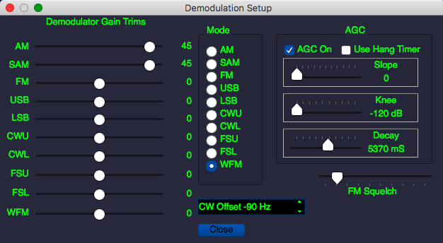
Demodulator Dialog
When adjusting the demodulator trims, it's is possible, when combined with a high VOL setting, to cause the audio to clip. The point of these sliders is to equalize the output of the various demodulators. You can do that by reducing the trim of the "louder" demodulators, rather than increasing the "quieter" ones, and that will prevent overload. Or, if you like, you can do it by increasing the "quieter" ones, but then you'll have to be careful how far up you push VOL
Another thing to be aware of is that the AGC setting can reduce the output level when a strong signal precedes a weaker one, thus making it appear that the demodulator output is low when it actually isn't. So if you want to accurately adjust the trim settings, you're well advised to shorten the AGC time down to a few hundred milliseconds.
- NETwork configuration dialog. This dialog lets you set the IP address and port where SdrDx should contact the IP server for RFSPACE and other USB SDRs such as the SDR-14 and SD-IQ.
- SouND configuration dialog. Lets you direct the audio output of SdrDx to the sound output device of your choice. Presently, the audio input choice has no function, but this may change in the future with the addition of general support for soundcard-style SDR hardware other than the FUNcube Dongle Pro.
LK - Load Memory Keys. This loads files containing data for all 25 memories.
SK - Save Memory Keys. Saves files containing data for all 25 memories.
- Store to memory or bandwidth (press this, then a memory or bandwidth button.) Press again to cancel.
- LoaD waterfall Palette definition file. See this page for details on the palette definition files.
AM - Select Amplitude Modulation (AM)
- Select Synchronous Amplitude Modulation (SAM)
- C-QUAM AM stereo decoding (works with ) You can →Right-click to access phase reversal and left-right channel swap options for the C-QUAM decoder.
FM - Select Frequency Modulation (FM)
- Select Wide Frequency Modulation (100 KHz.) Press repeatedly to change to and , then back to
- WFM Stereo High Blend. Right-click to configure.
- Disable WFM Stereo, receive monophonic audio.
- Reverse left and right channels in mode.
/ - Pink and White Noise generator, for use with setting WFM stereo high blend.
- Select Lower SideBand (LSB)
- Select Upper SideBand (USB)
- Select Lower SideBand Frequency Shift Keying (FSL)
- Select Upper SideBand Frequency Shift Keying (FSU)
- Select CW, Lower sideband (CWL)
- Select CW, Upper sideband (CWU)
- Scan memories. This function interacts with other controls. First, if is off, with the setting of SQL, which will control whether the scan stops or not. If is on, then the squelch value stored in the individual memories sets the stop level, rather than the setting of SQL. If is on, then I also stored in the individual memories, is recalled, rather than using the current setting of I. If is on, then also stored in the individual memories is recalled, rather than using the current setting of . If is on, then also stored in the individual memories, is recalled, rather than using the current setting of . If is on, then CWO also stored in the individual memories, is recalled, rather than using the current setting of CWO. If is on, then preset tuning steps are recalled from preset memories, rather than using the current manual setting of tuning steps. Only memories that have an active (bright) LED will be included in the scan.
- Sound output mute. If this is on, its LED will flash.
ZE - Calculate DC offset spike reduction.  ZRO will flash until the process is complete. →Right-clickZE in order to select automatic zeroing when changing VFOs and at startup.
- Transmit Squelch (mutes audio when received signal is large.) This is intended to be used as one way to mute the software in the presence of strong RF signals in a transmitting environment.
- "Squelch" (operates in AM, FM and SSB modes.) Uses a noise method for AM and FM when is off, or a level squelch method if is on. SSB only uses level-based squelch.
- Palette (waterfall) - color choice. There are two built-in palettes; with turned on, SdrDx will also try to load pal_default.wfp from the home directory. With it off, you get a black and white palette, and SdrDx will not auto-load pal_default.wfp; you can replace one with .
- signal SPEctrum - on or off. Save CPU/GPU energy, useful if you're just listening.
- Waterfall - on or off. Save CPU/GPU energy, useful if you're just listening.
- BaND markings on or off. SdrDx can place horizontal band markers along the RF signal display. Turn this on to see them.
- Memory SHow on or off. SdrDx can memory markers along the RF signal display. Turn this on to see them.
- "Notch" on/off (all 10 at once - for comparing notched audio against audio with notching disabled.)
- (RF) Notch Frequency Lock. This leaves the RF notches where you put them when you change the demodulator frequency. This allows notching out RF birdies and carriers while tuning around. For instance, if you are tracking a satellite transmission, the doppler shift will cause the signal to change frequency. If you set up the RF notches to remove the birdies, then turn on , then you can track the dopplered transmission and the RF notches will stay locked to the birdies.
- When on, causes any notch that is on, to turn off when you change the demodulator frequency.
- "Scale s-Meter" Lays a set of horizontal rules on the spectrum that correspond with s-meter readings.
- "Anti-Ringing" (makes SSB and AM sound better)
- "Noise Blanker" (RF DSP impulse noise reduction.) Works with NBT and NBW controls. This button has three states. When the noise blanker RF effects are displayed on the spectrum and the waterfall. When the noise blanker effects are not displayed on the waterfall, but they are applied to the signal demodulation. When the noise blanker is not operating.
- Dynamic Noise Reduction. Explained here.
- Transmit Squelch (mutes audio when received signal is large)
- "AM Squelch" (useful for intermittent channel use such as CB)
- Decay Log/Linear (changes AGC slider behavior)
- "Amateur PHone" (next/prev amateur band seeks phone/CW)
- TIMe station presets for control-F1...control-F10
- Level-based SQuelch. If on. Otherwise, noise-based.
- Memory SQuelch (allow memory recall to set squelch)
- Black User Interface (look and feel setting)
- Memory INtercept (allow memory recall to set plotter intercept)
- Memory Lowpass Filter (allow memory recall to set )
- Memory Highpass Filter (allow memory recall to set )
- Memory Tuning Steps (allow memory recall to set tuning steps)
- Memory Notch (allow memory recall to set the notch filters)
- Memory CW Offset (allow memory recall to set CWO)
- Save Waterfall File (PNG image in application directory)
- Set the clock to GMT
24 - Set the clock to 24 hour time
- TRacK peaks. Works in conjunction with TRK
- "Zero-On-1 KHz" (affects frequency widget behavior)
- "Zero-On-Click" (affects frequency widget behavior)
- "Zoom" - with this on, you can zoom in and our using ⇑ O and ⇑ P or and
- Enable / Disable memory frequency tooltip when main tooltips are off.
, , and are span memories. You set them manually with →Right-click, and recall them with →Left-click. You can also set them to the current span and grid interval by pressing first, then the button, or holding shift, and then pressing the button. If you hold control while pressing any span memory (...), the span will be set to the max span for the current sample rate, and the grid spacing to either 10, or the last grid setting specified in the setup dialog.
You can set arbitrary values using the span memories; this is particularly useful in conjunction with setting up the VFOs. For instance, you might want a 350 KHz span width, but the S- and S+ controls step directly from 300 KHz to 400 KHz - so the thing to do is configure a span memory to 350000 and then →Left-click it to set that specific span. Now the VFO has it memorized, and it will stay at that span unless you change it again.
through - Bandwidth memories. →Left-click or hold shift, then →Left-click the memory to store a new value.
→Right-click sets through to evenly spread steps between and
Bandwidth settings are managed per demodulator mode, so there are ten sets of seven memories, or 70 bandwidth memories in total.
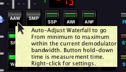
- Auto-Adjust Waterfall according to the signals inside the demodulator bandwidth. Hold the button down for as long as you want to sample; when you release it, the waterfall intercept and contrast will be adjusted accordingly.
- Sets up the trigger point for
- Sets up the trigger point for
- Scope ON - Enables or disables all scope activity.
- Clock ON - Enables or disables clock activity.
- Meter ON - Enables or disables all s-meter activity.
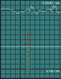
- SCoPe (audio) 2-channel standard scope, where channel 1 contains the demodulated audio signal, and channel 2 contains the S-Meter output and the AGC levels.
- X/Y scope for tuning bi-level frequency shift keying signals and observing stereo separation. Also can provide multipath tuning information when receiving in WFM mode.
- Demodulate 170 Hz shift, 45.45 Baudot radioteletype. See also the feature, just below.
→Left-click - Ignore NewLines. Creates a smooth word wrap for text received with the demodulator, or supplied via the TCP textline: command. →Right-click will clear the RTTY text area.
- AVeraGe (arithmetic mean of audio spectrum.) Right-click sets mix of mean with immediate impulse data.
- Smooth Noise Floor (RF Display); →Right-click sets smoothness and threshold
- Auto Noise Floor (RF Display) →Right-click sets threshold for , →Right-click sets smoothness
- VECtor display of audio spectrum
- WaTeRfall display of audio spectrum
3D - 3D audio spectrum scope display
RF/t - Raw RF and trapezoid for AM mode
- FIXed spectrum span (otherwise, spectrum is automatically matched to bandwidth)
- RTTY HI band (sets frequency knob to a range of 1500 hz to 4750 Hz in 5 Hz steps when on.)
- Calibrated SUNits indication for Ch2
- RATe for AGC/S-Meter channel 6.25 seconds/Div instead of 3.125 seconds/Div.
> - Play back previously recorded file (when Run off)
|| - Pause playback
- Rewind playback to zero
- Record file (when run on) ( →Right-click for settings)
CL - Clear (notches)
50 - 50 Hz multi-octave filter
60 - 60 Hz multi-octave filter
- Removal of Time Division Muliplex signal
- UI Color Settings
GS - Grid Spacing. Right click to step in reverse.
ZE - Zero the I/Q DC balance. If you see a spike at the center of the spectrum or waterfall, press this.
- Spectrum preset bandwidth
- Spectrum preset bandwidth
- Spectrum preset bandwidth
- Spectrum preset bandwidth
- Spectrum preset bandwidth
- Aux scope to standard 2-channel audio / signal mode
- Changes , , and 3D from dB (log display) to linear display. This may be more intuitive than the log (dB) display.
- Aux scope to RTTY shift monitor mode. Right-click to adjust RTTY scope gain.
- Aux scope to linear audio spectrum analysis mode
- Aux scope to circular audio spectrum analysis mode
- Aux scope to carrier analysis mode
- Aux scope to audio waterfall mode
3D - Aux scope to 3D spectrum mode
RF/t - Aux scope to AM RF / Trapezoid
- Pan tuning mode - and pan demodulator frequency from left to right and right to left instead of centering the demodulator the next span in the indicated direction. This is much more convenient for scanning bands continuously.
- Center tuning mode - signal shifts or holds fixed, demod shifts
- Demodulator On Waterfall. Right-clicking accesses controls for timeout and opacity.
- Spectrum Bandwidth. You can reduce the bandwidth of the spectrum and waterfall using this. Right-click sets the bandwidth limit and the threshold. Please note that limiting the bandwidth reduces displayed signal intensity of all information beneath the threshold and so affects display accuracy of the waterfall and spectrum. Usually in a pleasant way. ![]()
- Center current demod frequency
- Down spectrum by one window's width
- Up spectrum by one window's width
- Down spectrum by Hz indicated by #. These allow you to adjust and scan in the indicated frequency increments.
- Up spectrum by Hz indicated by #. These allow you to adjust and scan in the indicated frequency increments.
- Previous bandstack FIFO.
- Next bandstack FIFO.
N# - Notch filter enable. Each of these ten buttons turns an individual notch filter on or off.
5.33.4 - LEDs
 DUL The SDR and SdrDx are in dual-channel mode.
ST In mode, FM Stereo indicator.
RDS In mode, RDS data detected.
MDI, MDI - When flashing white or blue, indicates MIDI Learn mode active. Press ESC to cancel. Right-click for MIDI setup dialog.
TXS TXS - Transmit squelch is muting audio
SQL SQL - Normal squelch is muting audio
ZRO ZRO - I/Q Zeroing active: The receiver is trying to figure out how to compensate for DC level differences between the I and Q channels of the active SDR, or the incoming recording.
COR COR - Correction active: The correction available with a right-click on is actively being applied.
 TCP TCP - clients are connected to SdrDx
OVL (hardware and FFT overload) Reduce input signal levels!
PRE PRE - Spectrum presets available for control settings.
FRE RTTY / SITOR framing error indicator.
SYN SITOR SYNC indicator.
STA SITOR LOCK indicator.
5.33.5 - Other Controls
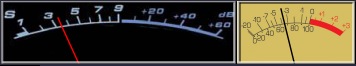
One of the many s-meter models
S-Meter - Received signal and AGC information display. See this page.
Demodulator Frequency
Top Large Numeric Readout - Demodulator frequency
Center Frequency
Bottom Large Numeric Readout - Center frequency
Decibels per division
dB/Div - Scale for main signal display
Top Reference
Max - Maximum signal at top of main signal display
Scrub Bar
Scrub Bar - for positioning RF file playback. The arrow on the bottom indicates and moves the playback position, using the left mouse button. On top, the arrows set the start and end playback positions, using the left and right mouse buttons respectively.
Info 1
Info Area 1 - Various status information
Info 2
Info Area 2 - Information about the frequency to which you are tuned
Info 3
Info Area 3 - Information about connectivity to the SDR
Aux Scope
Aux Scope - Various Audio and RF purposes
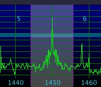
RF Signal Display
RF Signal Display - Shows all signals withing the span setting, which in turn is within the SDR bandwidth, and which are centered about the SDR's current operating frequency.
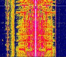
RF Waterfall Display - Shows activity in the RF signal display over time, adjusted to user taste for signal amplitude and floor, using a color palette to represent these related values.
| toc | index | guide | changes | keyboard | , previous | . next |